This release corresponds to version 1.5.7 of the GeoRiver software and replaces the release of version 1.5.6 published on 26 May 2023.
NEW FUNCTIONALITY
New functionality introduced in this release includes the below features:
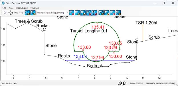
· Automating the calculation of tunnel length
The tunnel length is the distance between the selected VP point and intersecting point of the reach with a cross-section and this distance is currently calculated manually and added as text in Georiver. Automation of tunnel length calculation has now been facilitated in the software. When an invert/soffit marker is selected with a right click on a cross-section, it can be marked as the tunnel length identifier as shown below.
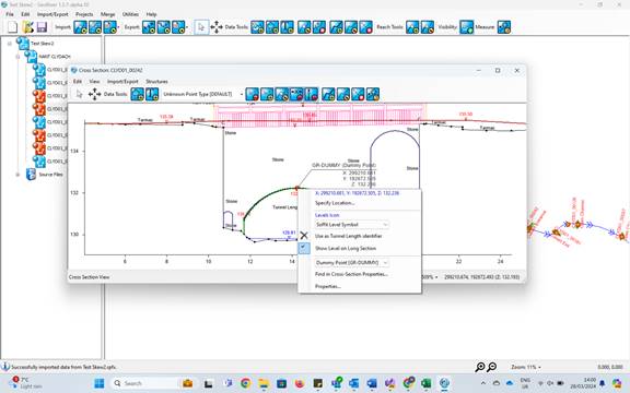
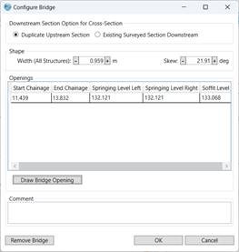
When a point is chosen as Tunnel length identifier in a cross-section, the tunnel length text would immediately get added to the XS form and would be removed once the option in the context menu is unchecked. The same would be populated in the width text box of Configure Bridge screen and Length textbox of Configure Culvert screen. When “use as TL identifier” or “show on LS” is selected in the above context menu, the menu will open once more automatically so that we have can make other choices along with it.
· Automating Skew angle Calculation
Skew angle calculation has now been automated in Georiver. Angle between perpendicular line of the centreline and cross section line in plan view is called the Skew Angle and will populate on the skew angle textbox in the Configure bridge form of the cross-section. The skew angle will be calculated, and diagram displayed on the cross-section as soon as the first bridge/culvert/deck is configured in a cross section and will not be removed until all the structures in the XS are cleared. The skew angle diagram will be drawn on the cross-section and exported to DXF file if it exceeds 5 degrees.
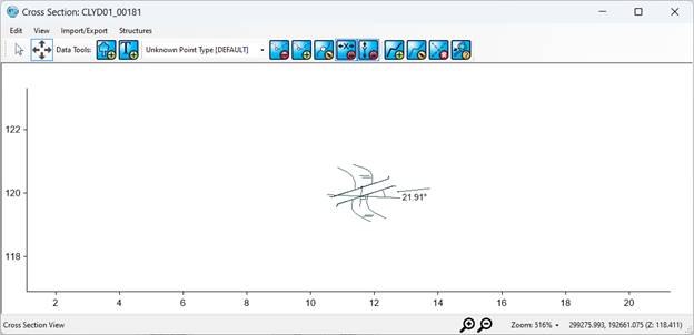
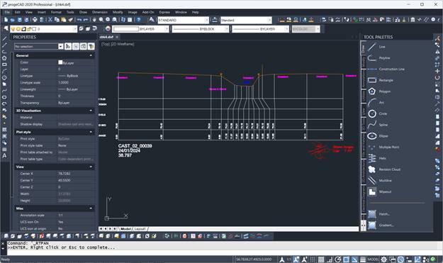
The DXF will display the skew angle diagram in its own layer in Red in the same line as that of the XS information section as shown below.
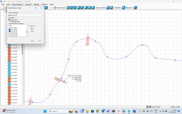
· Copy/Reassign triplet to other Cross-sections
A feature has been implemented in Georiver to facilitate copying and reassigning of any point in the plan view to other cross-sections. Once a point in the plan view is right clicked on Edit Survey Data mode, an option to “Copy/Reassign Triplet” can be seen as shown below.
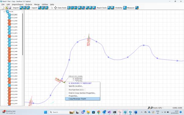
The popup allows the user to choose between Copying and Reassigning along with a list of all the available cross sections to choose from.
· Background Satellite Map Overlay
A feature has been implemented in Georiver to overlay Satellite map (Google API) as the background of the plan view similar to the DXF background overlay.
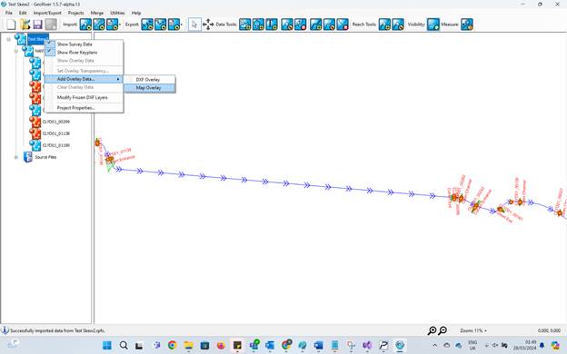
The Map overlay can be toggled using a switch as shown in the below image.
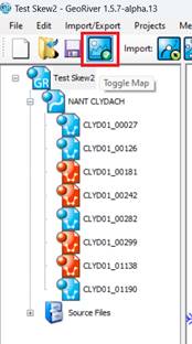
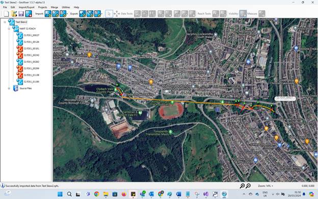
The map renders the centreline and cross sections as routes on the map overlay by matching the BNG coordinates recorded in Georiver with the WGS84 coordinates of Google Maps. The map can be dragged to pan using right mouse button and zoomed in/out by pinching in/out. The tooltip on the cross sections displays the XS name on hovering over them. Once the map is switched on, all the editing shortcuts on the toolbar are disabled as they do not work. The user can switch off map view if editing of the reach is required.
AMENDED FUNCTIONALITY
Amended functionality in this release includes:
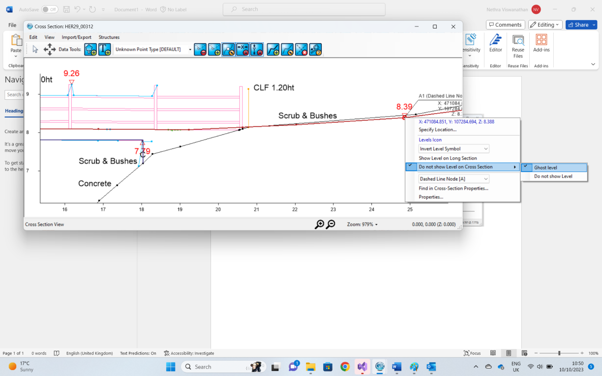
· Ability to toggle the presence of soffit/invert markers on Cross-sections
Level indicators displayed on a cross section can now be toggled to be visible/hidden/ghosted in the exported DXF file to avoid cluttering. When a level indicator is ghosted, it appears in a Ghosted layer in the resulting DXF file, and when the same is hidden, the indicator is not shown on the DXF.
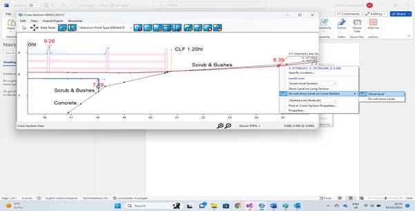
8.39 is ghosted and 7.79 is hidden in the exported DXF file.
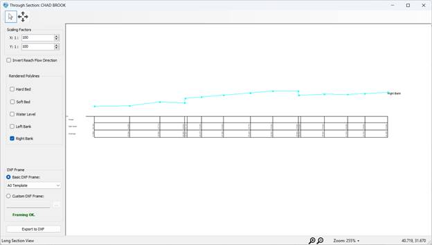
· Cranking and Polyline choices on Through sections
A facility has been implemented in Georiver to enable users to choose the polylines required to be displayed on a Through section. In addition to it, cranking lines have been introduced in the through section window and the final DXF export, so that the users do not have to make any edits with amending the overwriting in the exported file. Also, the inverted polylines which were not rendered as expected in the previous releases has been corrected.

The Polylines to be rendered are chosen via the checkboxes and the software requires atleast one polyline to be selected to render the through section.
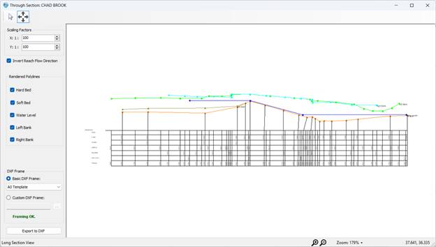
On inverting the reach flow direction, the polylines are displayed as required along with equally spaced measurements and cranking lines.
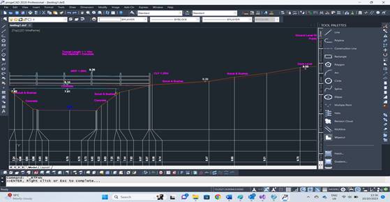
The DXF file also renders the Through section drawing with cranking lines and measurements which are equally spaced.
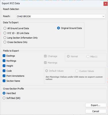
· XYZ Export of original ground data
A facility has been introduced in Georiver in the XYZ export window which will export original non-snapped ground data (BLA, crest, VBED, VLB, VRB etc) as seen in Project properties->Information Source.
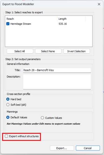
· FM Modeller Export of data without structures
A feature in Flood Modeller export window to export data without the structures in the cross-sections has been introduced in Georiver.
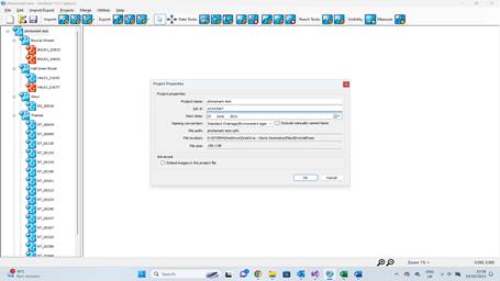
· Addition of Job number and Product code to exports
A job number field has been added to Project Properties window so that all exports can display the default filename with the job number while saving the files. The naming convention is as follows.
| Keyplan/Location plan | Job No_DPP_LP.dwg |
| Long Sections | Job No_DPP_LS.dwg |
| Cross Sections | Job No_DCS_XS.dwg |
| EACSD | Job No_FCE_EACSD_Reach name |
| XYZ outputs | Job No_FDA_XYZ_Reach name |
| HecRas/Flood Modeller/Infoworks | Job No_FCS_FM_Reach name/FCE_HecRas |
| Photo Schedule | JobNo_PGE |
If a job number is not specified under the Project Properties, the project name is used in the filename instead.
Job Number field in Project Properties Window
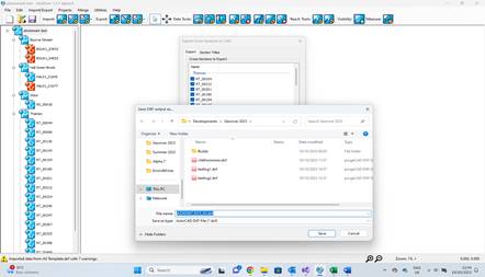
Export Cross-sections window
· HecRas export of low chord structure
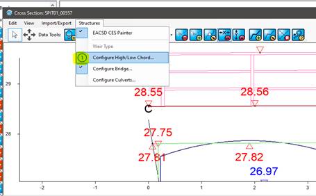
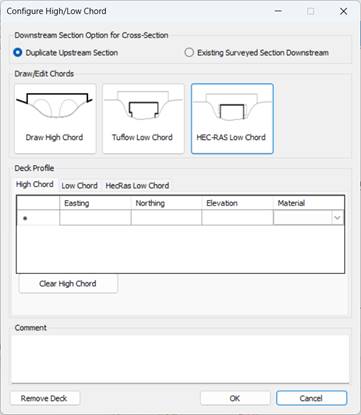
A facility has been introduced in Georiver to export low chord structure in place of Bridge structure when HecRas Export functionality is used. The software provides the facility to add HecRas low chord as a deck in a cross-section in addition to the existing low chord, exclusively for HecRas export. When a HecRas low chord is drawn along with a high chord, the software considers all the Hecras low chord points touching the hardbed as the start and end points(delimiters) of the bridge openings, thus deciding the number of bridge openings. For each opening, only forward chainages are allowed and the software snaps in case a backward chainage results while drawing the low chord structure as seen for BLA points.
In addition to the above, when High/Low chord is configured, the number icon changes according to the number of chords drawn (as shown below).
BUG FIXES
Bug fixes for this release include:
· Bridge Removal Issue fix
When a bridge is removed in the Bridge Configure window, the window will now be open until manually closed.
· CES Painter OK button fix :
The CES painter will now have an Ok button rather than using the X to close the window.
· Merge bug fix for orphan blocks:
When an orphan block is merged into a project, an exception is currently raised by the software with an error popup. Since orphan blocks do not have reaches associated until they are sorted into their construction lines, such blocks will now merge without reach association thus preventing the error.